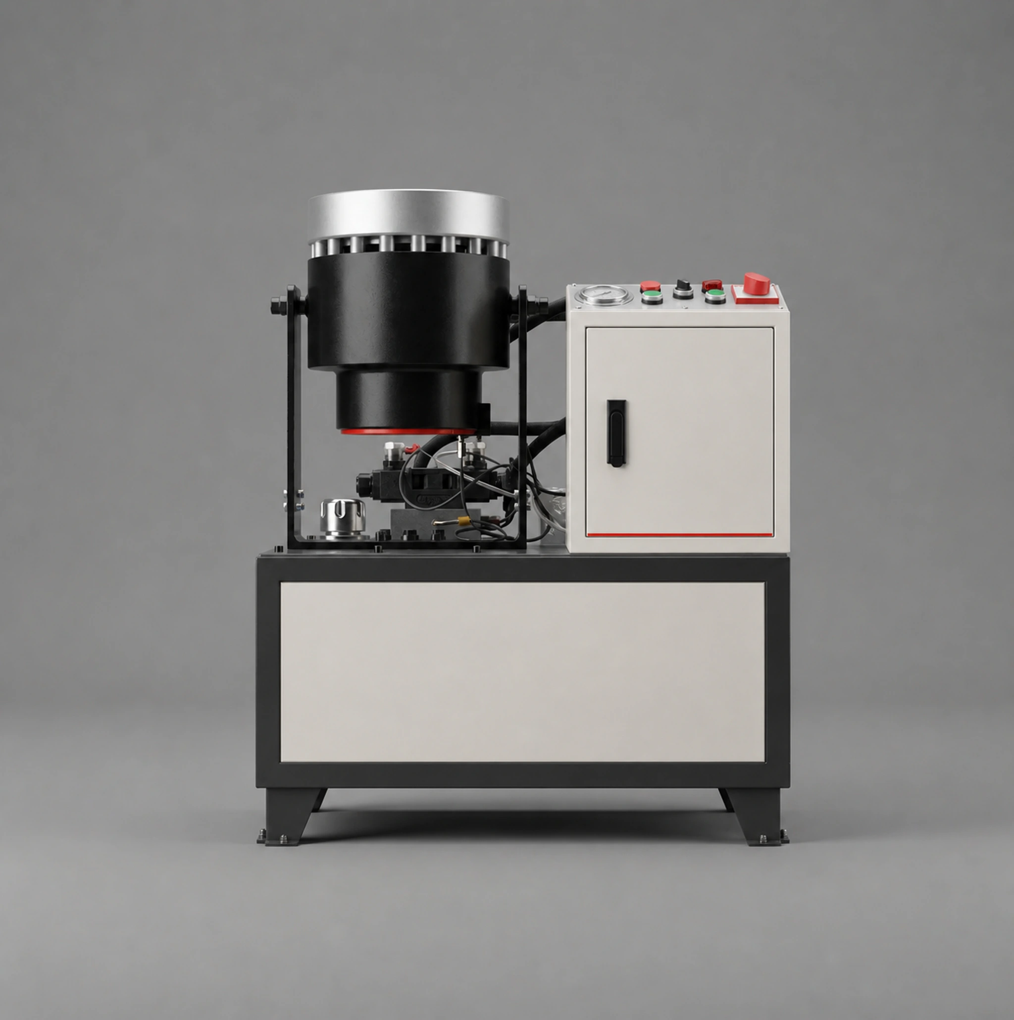
Used for end reduction of small and medium round tubes in furniture, fitness equipment and bicycle components. The formed end can support telescoping, welding, assembly or a subsequent forming operation, with different dies covering multiple tube sizes and end profiles.
Furniture Manufacturing
Fitness Equipment
Bicycle Tubes
Customization Scope
Tooling, stops, feeding and controls can be configured for the original diameter, wall thickness, material, target size, formed length and required cycle time. For thin-wall or appearance-critical parts, samples should be tested to confirm finish, roundness and springback.
Pipe Processing / Swaging
How the Machine Works
The round tube is positioned in the forming dies and the machine completes end reduction in a defined sequence. Die profile sets the main geometry, while positioning, feeding and springback influence formed length, roundness and repeatability.
Inputs Required for Selection
Incoming section, diameter or side size, wall thickness and length
Material grade, weld-seam position and incoming surface condition
Target end dimensions, formed length, finish and mating relationship
Tolerance, inspection method and required retained samples
Planned output, handling method, electrical supply and floor space
Configuration Options to Review
Workpiece-specific dies, positioning and support
Manual, semi-automatic or linked controls
Feeding, receiving and line integration
Local voltage, guarding and operator interface
Sample trials and parameter records for special parts
Trials and Acceptance
Inspect fasteners, lubrication, hydraulics, electrics and safety devices
Check no-load movement, control logic and emergency stops
Run material trials with the agreed workpiece
Measure critical dimensions and finish against drawings or samples
Confirm trial records, packing list and supplied information
Before Delivery and Installation
Confirm machine size, weight, unloading route and installation position
Prepare the specified power supply, foundation and working clearance
Check the main machine, dies, accessories and documents against the packing list
Complete safety and no-load checks before the first production trial
Maintenance Priorities
Check lubrication, hydraulic oil and fasteners according to the maintenance information
Remove debris and dust from dies, rolls or finishing zones
Record common settings, unusual noise, alarms and workpiece changes
Match machine identity, specification and photos before ordering a replacement
Frequently Asked Questions
Should a welded-tube seam be orientated?
A consistent seam orientation is recommended for larger reductions and appearance-critical parts.
Can one die cover every diameter?
Tooling normally matches the incoming diameter and target end form; any shared range must be confirmed by design.
✓
Success.
Thank you for your inquiry! Your request has been received.
Our engineering sales team will contact you within 24 hours.
⚠
Send Failed.
Sorry, there was a problem submitting your inquiry. You can try again, or contact us directly using the information below:
Please fill out the form with your requirements. Our engineering sales team will review your application and provide a detailed quotation for the selected machinery.